Sensational 10 Hp Motor Starter Typical Wiring Diagram

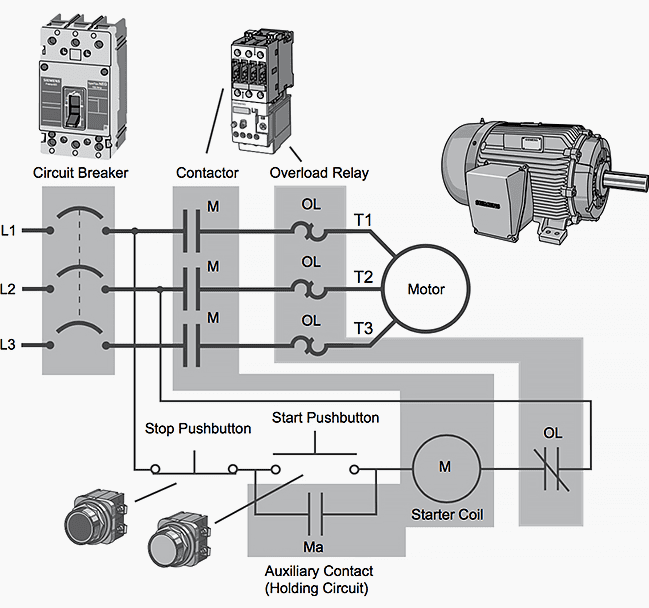
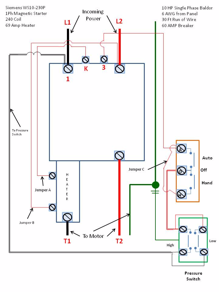
Figure 1 is a typical wiring diagram for a three phase magnetic motor page 5 62 1082112.
10 hp motor starter typical wiring diagram. Three phase motor connection star delta without timer power control diagrams. Each component ought to be placed and linked to different parts in particular manner. They do not indicate the physical relationships of the various components.
Pdf schneider electric wiring diagram. E0c 3 phase motor starter wiring diagram wiring resources. Star delta y δ 3 phase motor starting method by automatic star delta starter with timer.
Manual motor starters are simply manual switches designed to control larger current loads typical of motor control. Three phase motor connection schematic power and control wiring installation diagrams. In north america an induction motor will typically operate at 230v or 460v 3 phase 60 hz and has a control voltage of 115 vac or 24 vdc.
You might have a 480v sup ply that is attached to the line side of the starter and that runs through to the motor. Motor starter wiring diagrams print. Learn how a capacitor start induction run motor is capable of producing twice as much torque of a split phase motor.
These motor starters may be either single pole switch one line only or. Star delta starter for 3 phase motor. They may be small and similar to the light switches in your home or they may be much larger dedicated switches designed for control of high amperage circuits.
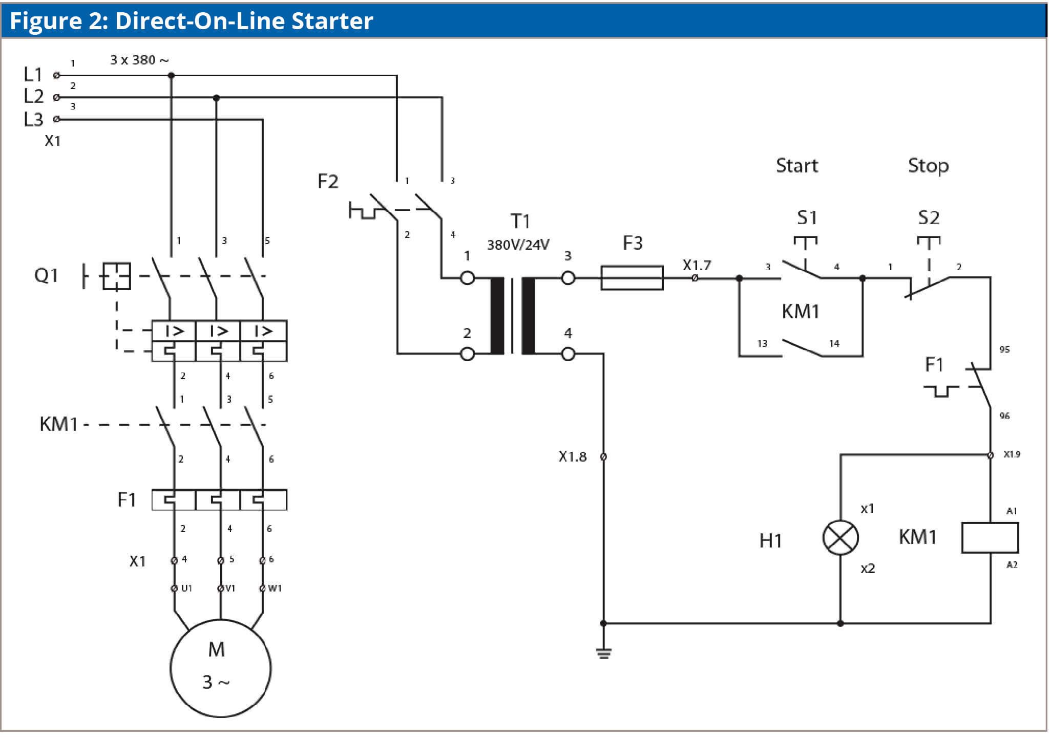
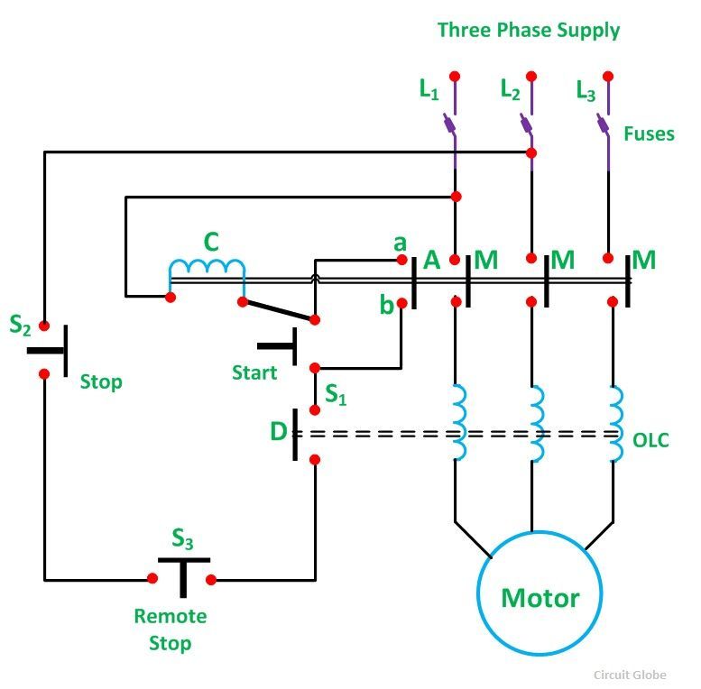
Line diagrams show circuits of the operation of the controller. 10 hp motor starter typical wiring diagram pdf 2017 07 09 original source basic wiring for motor control technical data guide eep basic wiring for motor control â technical data. Direct online starter dol starter.


