Awesome Honeywell T2 Thermostat Wiring

The o b wire can have many configurations.
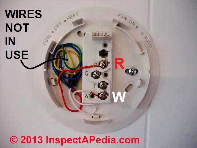
Honeywell t2 thermostat wiring. It can be w o b o b w o w b or you mayeven have separate o and b wires. At left the thermostat wiring diagram illustrates use of a honeywell t87f thermostat in a 3 wire application as a spdt single pole double throw switch such as used to control low voltage motors electric radiator valves zone valves. The wiring for your honeywell thermostat depends on the functions of your heating and cooling system.
For example in case a module will be powered up also it sends out the signal of half the voltage in addition to the technician will not know this he would think he provides a problem as this individual would. For the y y1 and y2 wires y or y1 will go to the y terminal and y2 will go to the y2terminal. Depress the tabs to put the wires into the inner holes of the corresponding terminals on the uwp one wire per terminal until it is firmly in place.
Gently tug on the wires to verify they are secure. Let s take a look at the g wire. You ll probably see a thermostat jumper wire connecting the rc and rh terminals.
It s there so you can supply power to the heating and cooling switches with a single wire which is usually red. This wire will go to the g terminal on your new thermostat. 12 connect remaining wires.
Use our helpful tool to take an assessment of the existing wiring in your home. In this video we show you how to install smart wifi thermostats like the honeywell rth9585wf including wiring setup and usage honeywell home rth9585wf1.


